

In close collaboration with the company Mycronic AB, FCC is developing novel software for simulation of the jet printing process used in the manufacturing of printed circuit boards. The software makes it possible for Mycronic to strengthen their knowledge of the complex jetting process and is supporting their product development of the next generation of jet printers.
In 1965, Gordon E. Moore observed the trend in the electronics industry that the number of transistors per integrated circuit doubles approximately every two years and made the prediction that this would continue also in the future. His prediction has proved to be more or less valid for almost five decades now, mainly driven by the tough competition between manufacturers that continuously push the development of electronic components to be smaller and faster. This rapid development could hardly have been sustained without efficient, flexible and highly accurate manufacturing methods, which, in turn, requires a thorough understanding of the process of mounting components onto the PCB (printed circuit board).
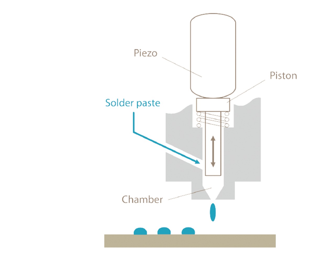
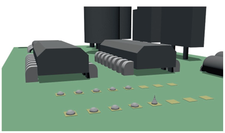
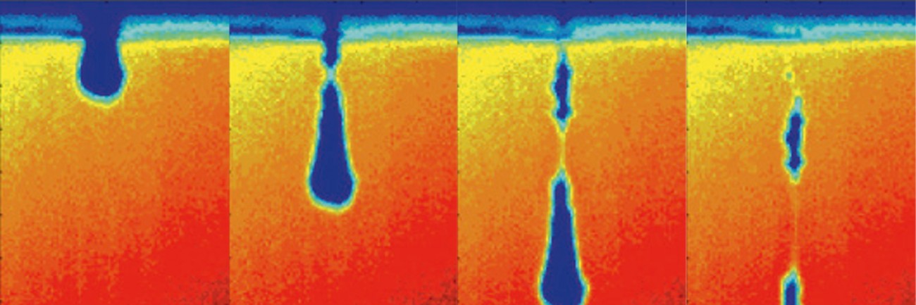
Before the components can be mounted, solder is applied onto the PCB. The components are then placed on their specific positions on the board with a placement robot and the PCB is heated such that the solder paste melts, adheres to the metalized pad and component and then finally cools to a solid joint. With the MY500 series, Mycronic has the capability to perform high precision jet printing of solder paste onto the PCB while the printer head is in motion. In this way they can produce a given pattern at higher speed than what would be possible with conventional methods. The driving force in the jet printer is a piezo element that expands rapidly when subjected to an electrical signal and causes a piston to accelerate. The movement of the piston results in a sudden increase of the pressure in the chamber, containing the solder paste, forcing the fluid to squeeze through the printing head nozzle. When the signal is cut off the piezo element retracts and the pressure decreases again. At this point, the momentum of the fluid is large enough to form a droplet that will travel through the air and impact on the PCB. This technique requires knowledge of the flow conditions inside the printer head, how the material behaves under these conditions and which parameters affect the droplet formation as the solder paste deposits from the printer head.
The solder paste consists of a mixture of solid granules and flux which makes the rheology of the fluid different from Newtonian fluids. Due to structural reorganization of the granules when subjected to deformation, the solder paste shows both visco-elastic and shear thinning behavior, meaning that the viscosity is dependent on the rate of deformation and on the time scales of the process. This non-Newtonian behavior is essential for the result of the jet printer. Due to the complexity of the solder paste and the small time and spatial scales of the process it is difficult to acquire experimental data of the jetting sequence. To perform simulations instead is an attractive alternative, but very challenging due to the large acceleration of the piston and strong fluid-structure interaction between the piston and the solder paste.
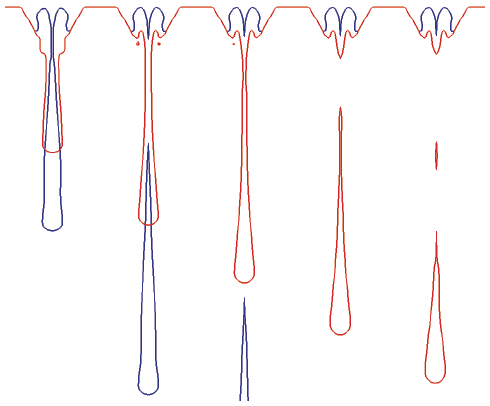
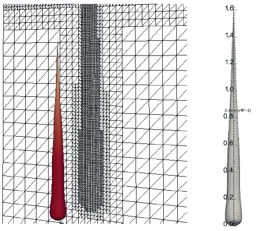
The simulations of the ejection and formation of the solder paste droplet are successfully performed with our in-house software IBOFlow (Immersed Boundary Octree Flow solver) coupled with LaStFEM (Large Strain FEM solver). The immersed boundary techniques and adaptive octree grids simplify the simulation setup and are perfectly suited for handling the complex fluid-structure interaction. The solder paste is modeled as a generalized Newtonian fluid with a time dependent Carreau model that takes both the visco-elastic and shear thinning behavior into account. Simulations show that the jet printing process is sensitive to material parameters such as surface tension and viscosity. In particular, the viscosity at high shear rates is important in the early jetting sequence, while the surface tension is more important for the droplet formation after the actual jetting event. Different piezo signals affect not only the droplet velocity and size, but also the filament breakup and formation of satellite droplets. The software’s ability to capture this is very promising since it is crucial for the quality of the solder joint.
The detailed modeling and short simulation times make it possible for Mycronic to use the software to gain better knowledge of the jetting process and in their development of the next generation of jet printers. In 2014, the work will for example include what happens with the material rheology before and in between the actual jetting events and how this affects the subsequent jetting. We also believe that a thorough understanding of the material properties is essential to the jetting performance and we will therefore continue our work on the rheology of complex fluids and improve our material models. This work also contributes to our ongoing efforts on simulation of laydown of sealing and adhesive materials.